Analysis of particles containing alpha-emitters in stagnant water at torus room of Fukushima Dai-ichi Nuclear Power Station’s Unit 2 reactor
May 16, 2022
Abstract
Particles containing alpha (α) nuclides were identified from sediment in stagnant water in the torus room of the Fukushima Dai-ichi Nuclear Power Station(FDiNPS)’s Unit 2 reactor. We analyzed uranium (U), which is the main component of nuclear fuel, using scanning electron microscopy (SEM). Other α-nuclides (plutonium [Pu], americium [Am], and curium [Cm]) were detected by alpha track detection and the morphology of particles with α-nuclides were analyzed by SEM-energy dispersive X-Ray (EDX) analysis. Several uranium-bearing particles ranging from sub-µm to several µm in size were identified by SEM observation. These particles contained zirconium (Zr) and other elements which constituted fuel cladding and structural materials. The 235U/238U isotope ratio in the solid fractions that included U particles was consistent with what was found for the nuclear fuel in the Unit 2 reactor. This indicated that the U of similar fuel composition had made finer. The α-nuclide-containing particles identified by alpha track analysis were several tens to several hundred µm in size. The EDX spectra showed that these particles mainly comprised iron (Fe). Since the amount of α-nuclide material was very small, Pu, Am, and Cm were adsorbed on the Fe particles. This study clarifies that the major morphologies of U and other α-nuclides in the sediment of stagnant water in the torus room of FDiNPS’s Unit 2 reactor differed.
Introduction
TEPCO’s Fukushima Dai-ichi Nuclear Power Station (FDiNPS) was severely damaged by the earthquake and resulting tsunami that struck on March 11, 20111. At the time, Units 1–3 of the six reactors were in operation, and the nuclear fuel in the Units 1–3 reactors was damaged. Seawater and freshwater were injected to remove the decay heat from the nuclear fuels. The water remained in the basement of the building, and the components of the nuclear fuel dissolved in it, resulting in highly radioactive stagnant water. The stagnant water contained radionuclides, such as fission products and actinides derived from nuclear fuels. A chemical treatment process was established to remove the radionuclides, and a recirculating engineering system was established to reuse the recovered cooling water. Since then, the amount of stagnant water has been gradually reduced, but it was discovered that the fine particles containing a higher concentration of Alpha (α)-emitting radionuclides were settling basement in the reactor building2. The concentrations of alpha-nuclides (102–105 Bq/L) in the stagnant water including sediments were higher than the cooling water in the downstream building. Alpha-emitting radionuclides such as uranium (U) and plutonium (Pu) can cause serious internal exposure upon entering the human body. Alpha-nuclides should be strictly controlled when compared to caesium(Cs)-137 and strontium(Sr)-90, which are the main nuclides in fission products. Technology must be developed to effectively remove the alpha-nuclides from the stagnant water. For this purpose, we collected stagnant water in the torus room in the basement of the reactor building of Unit 2 and conducted radiochemical analysis of the precipitates in the stagnant water.The stagnant water is a higher concentration compared with what was detected at the entrance to the Cs adsorption system. In addition, the presence of α-emitting radionuclides was confirmed in the samples containing mixed sludge components from the stagnant water in the reactor building. To proceed with the treatment of the stagnant water deep inside the reactor building in the future, a better understanding is required of the different types of α-emitters, particularly those included in particulate solids in the stagnant water.
In existing research, radioactive particles containing U were detected in association with Cs microparticles (CsMPs) outside the FDiNPS site and their physicochemical composition and morphology were analyzed3,4,5,6,7,8. Abe et al.3 collected CsMPs emitted from the FDiNPS from the atmosphere and analyzed them using synchrotron radiation X-rays to detect U in the CsMPs. Ochiai et al. detected U particles of several hundred nm in CsMPs by scanning electron microscopy-X-ray detection (SEM-EDX) analysis. Their results reflected the composition of UO2 on magnetite by observing the diffraction pattern obtained using transmission electron microscopy. Similarly, diffraction patterns of UO2 and zirconia were obtained from mixed particles of Zirconium (Zr) and U in CsMPs, respectively. This indicated that U was present in CsMPs in both UO2 nanocrystals and U-Zr nanocrystrals forms6. Kurihara et al.8 found that the U in the fuel composition of the Unit 2 reactor was present in the CsMPs by analyzing the isotope ratios of 235U and 238U in the CsMPs using nanoscale secondary ion mass spectrometry. The release of fuel-derived Pu into the environment has also been reported by soil analysis9,10,11,12,13, airborne particles14, and CsMPs7. For americium (Am) and curium (Cm), few reports have been published regarding their release into the environment11. Recently, Morishita et al.15 detected particles containing α-emitters in smear samples collected from inside the FDiNPS using an α-ray imaging detector. The maximum energy of the α-rays indicated the presence of 238Pu; γ-ray spectra indicated the presence of 241Am. The morphology of these α-emitters was not observed.
In this study, we analyzed the concentrations and forms of U and other α-emitters in liquid and solid phases to obtain the basic data necessary for considering a removal method for α-emitters in the stagnant water of Unit 2 of the FDiNPS. The search for radioactive particles in existing studies was conducted primarily using imaging plate (IP)4 or sodium iodide scintillation counters8,16 and by detecting γ-rays from CsMPs. However, while these methods are effective for CsMPs with high radioactivity, it is difficult to selectively detect α-emitters that are present in small amounts and with low specific radioactivity. Therefore, we decided to use a combination of an automated particle measurement method using SEM-EDX17 and a method for detecting particles containing α-emitters using solid-state track detectors18,19,20,21,22,23,24
Results and discussion
Particle size distribution of solids in the stagnant water containing uranium and alpha-emitters
Figure 1a shows a schematic of a sampling location of a stagnant water sample in this study. Figure 1b shows how the particles settled after the sample was collected. The reddish-brown particles had settled over time. The solids in the stagnant water were classified and the U concentration of each fraction was measured by inductively coupled plasma mass spectrometry. The results are shown in Table 1.


As indicated, 238U was quantified in all fractions of all particle sizes, indicating its existence in various particle sizes. More than 99 % of U was present in fractions larger than 10 μm. The 235U/238U isotopic ratio was approximately 1.9 %, which closely matched the Unit 2 composition (1.93 %)25. Analysis of the total α-activity in each fraction showed that more than 99.8 % of the α-emitters were present in fractions larger than 10 μm (see Supporting Information, Table S1). These results suggested that most of the U and α-emitters in the stagnant water sample of the Unit 2 were present in particle fractions larger than 10 μm. Accordingly, a search for particles containing U and α-emitters was attempted using particles in solid fractions.
Detection and composition analysis of uranium particles using scanning electron microscopy-X-ray detection
As the main U isotopes (235U and 238U) in the fuel composition have a long half-life and low specific activity, SEM-EDX was adopted to detect U-rich particles. Precipitates on the filter with a pore size of 5 μm were loaded onto carbon tape (Fig. 1c) and observed by SEM-EDX. Particles containing more than 3 % U by atomic ratio (hereafter referred to as “U particles”) were detected based on the results of elemental composition analysis. An example of the observation result of UP1 is shown in Fig. 2.

Black particle (UP1) was observed on top of the reddish-brown particles in the center of optical image in Fig. 2a. Figure 2b shows a backscattered electron detection(BED) image of the same region as Fig. 2a. In the BED image and its magnified view (Fig. 2b, c), the black particle in Fig. 2a had a high intensity. In general, a particle containing an element with a relatively higher atomic number yields a BED image with higher brightness. The particle (UP1) with high brightness in Fig. 2b, c should contain heavy element. The peaks at 3.18 keV (U Mα), 3.34 keV (U Mβ), and 3.55 keV (U Mγ)26 were observed within the EDX spectrum of the UP1 particle (Fig. 2d), indicating that the particle included U. According to the results of SEM-EDX composition analysis of the U particles (UP1 in Table S2), U was the main component. In addition, the distribution of components in the fuel-structure materials, such as Zr and Cr, was also observed on the U particle (Fig. 2e). In contrast, iron (Fe) was observed to have been distributed around the U particles, indicating that the U particles were attached to the Fe particles. These results suggested that the U particle would be particulate with fuel-structural materials.
Using the same procedure as in the above paragraph, 14 U particles were detected. The observed particle sizes and the elemental maps of U and Zr are shown in Fig. 3a. Elemental composition of U particles are shown in Table S2.

Uranium particles with size ranging from approximately 500 nm to 3 μm were observed. Uranium particles were attached to Fe particles or present on their own (Fig. S1). The content of Fe in the analyzed stagnant water sample was approximately 4,400 times higher compared with U, indicating that the main component of the filtered material was Fe. Uranium particles smaller than the filter pore diameter of 5 μm were trapped, suggesting that they were cake-filtered during centrifugal filtration.
The isotope ratios of U in this fraction were consistent with the fuel composition derived by ICP-MS measurements. The presence of U particles with an isotopic composition the same as the nuclear fuel suggested that these U in the stagnant water sample had been derived from reactor core. The release of U and Pu from the FDiNPS into the environment was investigated and clarified by analyzing bulk soil samples for Pu9,10,11,12,13 and measuring the isotopic composition of U3,6,9 and Pu particles7 associated with CsMPs. Fine U, U, and Zr particles, ranging in size from several tens of nm to several hundreds of nm, have been detected in association with CsMPs in the environment6. In the present study, it was found that particles approximately 10 times larger in size than the particles associated with CsMPs existed in the stagnant water sample. It was also clarified that some U particles were not associated with CsMPs but existed independently.
Many U particles included Zr, which would have been derived from cladding. The ratios of U and Zr in these particles are compared in Fig. 3b. The ratio of U to Zr in each particle varied. In addition, in some particles, Zr was not detected, suggesting that the particles retained their fuel form. An existing report6 suggested the existence of two types of U particles several hundred nm in size that had been derived from the FDiNPS and released into the environment; one of these particles was in the fuel form of UO2 and the other presented as a Zr mixed oxide.
Detection and analysis of particles containing alpha-emitters using alpha track detection
The distribution of α-emitters in solids was investigated using alpha track analysis. An example of α-emitter particles and observed alpha tracks is shown in Fig. 4a, b. The upper left part of the particle in Fig. 4a shows the presence of U particles UP10 and UP13 (Fig. 4c, d), which are identical to those shown in Fig. 3. The distribution of alpha tracks can be observed uniformly from the reddish-brown particles; the uneven distribution of the position of U particles is not presented. Only a few tens of alpha tracks were observed, even for the alpha tracks at the position of the UP1 particle (Fig. S2), which had the largest particle size among the detected U particles with a diameter of 3 μm (Fig. 3a). In comparison, several hundred alpha tracks can be observed in Fig. 4b. This result suggested that the main source of alpha tracks was not U particles but other α-emitters on the reddish-brown particles.

The particle with the most alpha tracks is shown in Fig. 5a, and the alpha tracks derived from this particle are shown in Fig. 5b. The SEM-EDX observation of this particle is shown in Fig. 5c. Three particles can be observed in this image, all of which were found to comprise mainly Fe, based on the elemental mapping results (Fig. 5d, e). Furthermore, the elemental analysis results showed that U and other α-emitters were not detected (Fig. 5d). An almost uniform distribution was observed of α-nuclides on the Fe particles; this indicated that the α-nuclides present in ionic form in the solution may have focused on the Fe particles.

Uranium was also detected in the fractions smaller than 10 μm; however, α-emitters were only detected in fractions larger than 10 μm (Table S1). As Fe particles were in much larger quantities and sizes than U, the most of Fe particles were present in fractions larger than 10 μm by cake-filtration. As a result, most of the α-emitters, such as Pu, Am, and Cm, were observed the fraction lager than 10 μm, although fine U particles were present in each fraction. Iron particles (Fig. 5) were approximately 100 μm in size, which were smaller than those in Fig. 4 (approximately 200 μm). The number of alpha tracks was much larger among the Fe particles in Fig. 5 than in Fig. 4. Thus, the amounts of α-nuclides were not proportional to the size of the Fe particles but varied between particles. As noted above, the contribution of U particles to the alpha tracks was minimal (Fig. S2), and the number of other α-emitters in U particles was negligible compared with the total amount of α-emitters.
Among the three particles, the IP1 particle, i.e., the main source of the alpha tracks, had been dissolved and α-ray measurements were performed. Figure 6 shows the α-ray spectra of the IP1. Alpha nuclides such as 239Pu, 240Pu, 241Am, and 244Cm were detected. For the particle analyzed in this study (IP1), the radioactivity ratio of 238Pu + 241Am to 239Pu + 240Pu was 4.03, and the ratio of 244Cm to 239Pu + 240Pu was 1.17, which was almost consistent with the fuel composition (4.50 and 1.14, respectively)25. Future work should clarify whether the variation of nuclides exists in each Fe particle.

Estimation of the chemical properties of uranium and alpha-emitter particles using micro-Raman spectroscopy
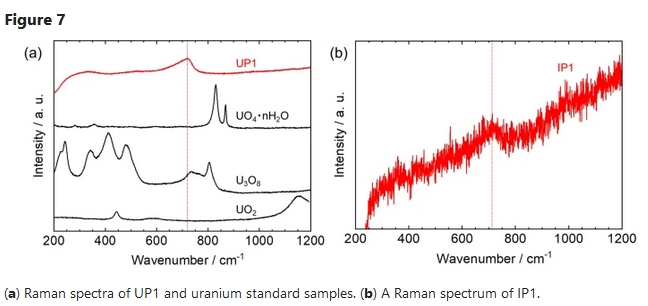
A Raman spectrum of the UP1 particle was obtained by micro-Raman spectroscopy. Figure 7a shows the Raman spectra obtained from the UP1 and uranium standard samples. The Raman peak of UP1 is located at approximately 730 cm−1, suggesting that it is in a different chemical state from UO2 and other U oxides. Figure 7b shows the Raman spectrum obtained from IP1. A Raman peak is only located at approximately 710 cm−1. Hanessh reported that natural ferrihydrite has only strong 710 cm−1 band27.The Raman spectrum of IP1 showed that the surface of the Fe particles existed as ferrihydrite. Since the pH of the stagnant water sample was almost neutral and the adsorption of Pu28,29 and Am29 on Fe oxides was previously reported, the ions or colloids of these α-emitters would be adsorbed onto the Fe particles. Accordingly, it is suggested that α-nuclides are distributed on Fe oxides.
Conclusion
To eliminate the presence of α-emitters in the stagnant water, the particles were collected according to their size. Uranium particles were detected by SEM-EDX. Other α-emitters (Pu, Am, and Cm) were detected using alpha track detection and measured via alpha spectrometry. The average isotopic composition of U in the stagnant water sample match well with the fuel composition of FDiNPS’s Unit 2. The U particles in this sample were up to 10 times larger in size than those observed in the environment. It was also shown that Pu, Am, and Cm α-emitters were adsorbed onto Fe particles. These results demonstrated that the major morphology of U and other α-emitters was different. By understanding these types of α-emitters, important information was obtained for considering the separation method of α-emitters in the treatment of the stagnant water in the Unit 2.
Methods
Sampling of stagnant water in the torus room of FDiNPS’s Unit 2
A 40-mL of stagnant water sample in torus room of FDiNPS’s Unit 2 was provided form TEPCO HD. The stagnant water containing sediment accumulated on the basement floor was collected with a water sampler at 30th June, 2020.
Classification of solids and the distribution of uranium and alpha nuclides in the stagnant water
A 2-mL sample of the stagnant water was collected with a stirring well and transferred to a centrifugal ultra-holder (UHP-13C; Advantec) equipped with a 10 µm pore-size membrane filter (PTFE, o.d.13 mm; Merck). This centrifugal ultra-holder was set in a centrifugal separator (CN-820; Az-one) and centrifuged at a rotation speed of 3000 rpm for 10 min to separate the residue from the filtrate. The filtrate was sequentially filtered through 1, 0.1, and 0.02 µm filters. To dissolve the α-emitters in the residue and filtrate, each sample was transferred to a quartz beaker. Nitric acid (HNO3) and hydrogen peroxide (H2O2) solutions were added to the residue and the filtrate on the filter to create a 2 M HNO3–2% H2O2 solution, which was heated and dissolved on a hotplate at 130 °C for 1 h. Since the 0.02 µm pore size of the Anopore membrane filter (0.02 µm pore size; Whatman) was dissolved by HNO3 and the impure U contained by the filter was eluted, determination of the residue in the 0.02-µm section was derived from the difference in U concentration in the filtrate of the 0.1 and 0.02 µm filters. The heated sample solution was passed through a UTEVA-Resin column (UT-C20-A; Eichrom) conditioned with 6 mL of 2 M HNO3; 15 mL of 2 M HNO3 was used to wash out impurities in the column, and 10 mL of 0.01 M HNO3 was passed through to elute U adsorbed in the column. The collected eluate was heated on a hotplate at 130 °C until just before it dried up and then re-dissolved in 5 mL of 0.32 M HNO3 to make the solution for the ICP-MS measurement. Quantitative analyses of 235U and 238U were performed by ICP-MS (7700x ICP-MS; Agilent) in the “no-gas” mode using the calibration curve method with a natural U solution. The same procedure was repeated two times (sample name: SW-1,-2).
Detection of particles containing alpha-emitters using a solid-state nuclear detector
A 1 mL sample of stagnant water was taken and particles were collected by centrifugal filtration using a filter with a pore size of 5 µm (Millipore). Some of the collected particles were transferred to a carbon tape attached to an aluminum sample table using micro spatulas. The sample was placed on top of a solid-state track detector (TNF-1; Hartzlas) and exposed to alpha-rays from the sample for 19 h. Following the exposure, the detector was etched with a 7 M sodium hydroxide solution at 70 °C for 3 h. After the etching process, the detector was ultrasonically cleaned three times using ultrapure water and dried with a clean wipe. The alpha tracks created on the solid-state track detector were observed using an optical microscope (VHX-5000; Keyence), and the location of the particles with high concentrations of α-emitters was identified. The identified α-rich particles were analyzed to observe their composition using SEM-EDX (JEOL, JCM-7000).
Each of the three particles in the spot where the largest number of alpha tracks were observed was transferred onto a 5 mm square silicon (Si) chip using a micromanipulator (QP-3RH; MicroSupport). The micromanipulator was attached to a sampling tool (MTW-1; MicroSupport) and set with micro tweezers (TW-2525; MicroSupport). Under observation using a ×100 to ×1000 objective lens (VH-Z1000R; Keyence) in a microscope, the microparticles were separated using the micro tweezers and placed on the Si chip. The Si chip loaded with the microparticles was transferred to a quartz beaker using ceramic tweezers (TA-CK-20; Toray). Then, 2 mL of 2M HNO3 + 2% H2O2 was added to the beaker and heated on a hotplate at 150 °C for 1 h to dissolve the microparticles, then it was heated on a hotplate at 180 °C for approximately 1 h. Next, The Si chip was cleaned while removing it from the quartz beaker using 5 mL of 0.5 M HNO3. The mixture of sample and the rinsing solution was re-dried on a hotplate at 180 °C for approximately 1 h and 30 min. Next, 2 mL of 0.5 M HNO3 was added and the sample was heated on a hotplate at 180 °C for approximately 30 min. When the sample solution was approximately 0.1 mL, it was removed from the hotplate. The sample preparation was performed by heating a sample holder for α-ray measurement (o.d.20 mm, stainless steel) at 100 °C, then dropping the sample solution to spread it in the center and baking it on the sample holder.
Detection and analysis of uranium-containing particles using scanning electron microscopy with energy dispersive X-ray analysis
The same sample that had been used to complete alpha track analysis was used for U-containing particles larger than 0.5 µm in diameter using the automatic particle finder17 of the SEM-EDX. First, the field of view was fixed by observing the back-scattered electron image of part of the sample for observation at a magnification of ×1500. Then, in the field of view, the lower limit of brightness was set so that heavy elements beyond Zr could be detected; heavy element particles were automatically detected. The detected particles were automatically elementally analyzed and identified as particles containing more than 3% U by atomic ratio, based on the results of elemental composition analysis. For each U particle detected by the automated particle finder, EDX mapping analysis was performed to determine the elemental composition of U particles. The U and Zr ratios were calculated from the intensity of the 3.18 keV (U Mα) and 2.04 keV (Zr Lα) lines, which were obtained from the EDX spectra of the U particles.
Microscopic Raman spectroscopic analysis of uranium particles and alpha-emitter particles
The micro-Raman spectrometer (Micro-RAM 532A; Lambda Vision Inc., Japan) used in this study was equipped with a 532-nm neodymium-doped yttrium aluminum garnet laser and a Raman charge-coupled device detector. The laser was focused onto the sample using a ×100 magnification objective lens. The laser power at the sample position was measured using an optical power meter (3664; Hioki Inc., Japan). In this study, the laser power at the sample position was adjusted to 0.4 mW for the measurement of U particles. The acquisition times measured 60 s. Each spectrum made of five accumulations was acquired for each particle. For the measurement of each standard U particle, the laser power at the sample position was adjusted to 0.03 mW. The acquisition times measured 60 s. Each spectrum made of ten accumulations was acquired for each uranium particles. For the measurement of α-emitter particles, the laser power at the sample position was adjusted to 0.1 mW. The acquisition times measured 10 s. Each spectrum made of five times was acquired.
Data availability
The data that support the findings of this study are available from Tokyo Electric Power Company Holdings Inc. but restrictions apply to the availability of these data, which were used under license for the current study, and so are not publicly available. Data are however available from the authors upon reasonable request and with permission of TEPCO HD.
To read more: https://www.nature.com/articles/s41598-022-11334-1
TEPCO to Remove Contaminated Pipes at Fukushima Daiichi Nuclear Power Plant by “First Half of FY2022” Due to Continuing Troubles

April 18, 2022
On April 18, at a meeting of the Nuclear Regulation Authority to review the status of the accident at the Fukushima Daiichi Nuclear Power Plant, TEPCO announced that it had changed its target date for the completion of work to “the first half of FY2022 (April to September)” regarding the removal of pipes between Units 1 and 2 that were contaminated with high concentrations of radioactive materials. Previously, the target was “within FY 2009. The scope of the removal work includes the areas that interfere with the installation of rainwater inflow countermeasures in the waste treatment buildings of Units 1 and 2 and the installation of a large cover in Unit 1.
The removal work began on February 24, but has not progressed at all due to a series of problems with the cutting equipment. The timing for the resumption of work is not clear, as investigations are still underway to determine whether the cutting equipment and method used to lift the pipes up by a large crane are appropriate.
The pipes to be removed were used in the venting process immediately after the accident to release contaminated air inside the reactor to prevent the containment vessel from rupturing. The pipes are 30 cm in diameter and measure 65 meters on the Unit 1 side and 70 meters on the Unit 2 side. The current plan is to cut the piping into 26 sections and remove them. The surface dose at the connection with the exhaust stack is 4 sievert per hour, which is high enough to kill a person if he or she stays there for several hours. For this reason, all work will be carried out remotely. (Shinichi Ogawa)
https://www.tokyo-np.co.jp/article/172472?rct=national&fbclid=IwAR1DYTcIpK–IpNqQfheOVBWKG8-G1Eonb274DLuS8FOMWxZ9ciYQLdmaiM
A Step Toward Fuel Debris Removal: Robotic Arm Arrives at TEPCO’s Fukushima Daiichi Nuclear Power Plant

January 31, 2022
Akira Onoda: “The robot arm, which weighs 4.6 tons, is about 8 meters long when folded, but when a device is attached to the end, it can extend up to 22 meters. It can extend up to 22 meters.
On the morning of March 31, the robot arm was brought to Naraha Machi. The development of the arm in the UK was delayed for a year due to the new corona, but the final test will be conducted at the facility in Naraha Machi.
Akira Onoda: “The robotic arm will be placed in the upper part of the facility that mimics the interior of Unit 2 here, and will pass through a hole 55 centimeters in diameter to enter the pedestal where the debris is located.”
<(Image)
First, the telescopic arm is extended to enter the containment vessel. It is assumed that the tip of the arm, which is equipped with a device for extraction, will be used to access the bottom where the debris is located. The final test will be conducted over a period of six months from mid-February using a full-scale model.
Tomoki Kamigaki, chief engineer of MHI’s Decommissioning Project Office: “One important thing is that the device works exactly as we intend it to, so we think it is important to make sure that both the device and the operating system are working properly.
The only thing we know about the fuel debris is that even in Unit 2, the most advanced reactor in the study, it is possible to grab and lift some of it. The only thing we know about the fuel debris is that it can be grabbed and lifted, even in the Unit 2 reactor, which is the most advanced.
Akira Ono, President of TEPCO’s Fukushima Daiichi Nuclear Decommissioning Promotion Company: “I think we will start with a small amount of fuel debris, maybe one or two grains. I think we will be able to understand what the fuel debris is through analysis. I think this is the first step.
TEPCO plans to start removing fuel debris from the Unit 2 reactor by the end of 2022.
Fukushima TV
Robot for removing nuclear fuel debris at Fukushima Daiichi
19 janv. 2022
Footage of a robot developed to remove nuclear fuel debris from the No. 2 reactor at the Fukushima Daiichi nuclear power plant is released.
Fukushima Daiichi Unit 2 Spent Fuel Removal Process
December 23, 2021
TEPCO has been progressing with the preparation work for the eventual removal of the spent fuel from unit 2 at Fukushima Daiichi. New details of the fuel removal process have also been released.
Spent fuel removal is scheduled to begin in 2024 and be completed by 2026. Further decontamination work inside is underway as is work outside the building to remove debris and prepare the ground for the spent fuel removal building. The control room on the refueling floor is slated for removal to make way for the opening between the refueling floor and the new spent fuel removal building to be constructed.

Decontamination work on the refueling floor is underway. Starting in January 2022 shielding materials will be installed on the refueling floor.

Shielding appears to be slated to go along certain walls and over the reactor well area. The existing spent fuel crane will be moved over the reactor well to make room for the new fuel handling crane.

Spent fuel removal building progress as of December 2021

The floorplan (below) shows a tall shielding system to be installed around the spent fuel pool area, isolating it from the reactor well. This will act as a shielded access hallway for workers to enter the area. The floorplan also shows the spent fuel removal building where it will be installed adjacent to the spent fuel pool.

The shielding locations are shown in green in the diagram (below).

Ground foundation work is underway near unit 2 for the spent fuel removal building. This work is being done with remote equipment due to the radiation levels between units 2 and 3. The levels are still considered too hazardous for human workers a decade after the initial disaster.

The original TEPCO report in Japanese can be found here.
All original images credit, TEPCO.
Ikata nuclear reactor to be shut down – 40 year decommissioning process
Regulator approves Ikata 2 decommissioning plan
Japan’s Nuclear Regulation Authority (NRA) today approved Shikoku Electric Power Company’s decommissioning plan for unit 2 of its Ikata nuclear power plant in Ehime prefecture. Decommissioning of the unit is expected to be completed by 2059.
07 October 2020
Ikata 2 is a 538 MWe pressurised water reactor that began operating in March 1988. It was taken offline in January 2012 for periodic inspections. Shikoku announced in March 2018 that it did not plan to restart the reactor. It said the cost and scale of modifications required to upgrade the 40-year-old unit to meet the country’s revised safety standards made it uneconomical to restart it.
The utility submitted an outline of its plans for decommissioning the unit to the NRA on 10 October, 2018. Shikoku also submitted requests to Ehime prefecture and the municipality of Ikata, as specified under nuclear safety agreements concluded with those authorities.
Following a review, which included a total of seven public meetings, the NRA has today approved the decommissioning plan for Ikata 2.
According to the plan, decommissioning of the unit will take about 40 years and will be carried out in four stages. The first stage, lasting about 10 years, will involve preparing the reactor for dismantling (including the removal of all fuel and surveying radioactive contamination), while the second, lasting 15 years, will be to dismantle peripheral equipment from the reactor and other major equipment. The third stage, taking about eight years, will involve the demolition of the reactor itself, while the fourth stage, taking about seven years, will see the demolition of all remaining buildings and the release of land for other uses.
During the first stage, all fuel is to be removed from the unit. This includes 316 used fuel assemblies that will be sent for reprocessing and 102 fresh fuel assemblies that will be returned to the fuel fabricator.
“In the future, we will obtain the consent of Ikata Town and Ehime Prefecture, based on the safety agreement,” Shikoku said.
Shikoku decided in March 2016 to decommission unit 1 of the Ikata plant, also a 538 MWe PWR, which began commercial operation in September 1977. That unit had been taken offline in September 2011 for periodic inspections. Upgrades costing more than JPY170 billion (USD1.5 billion) would have been needed at the unit in order for it to operate beyond 40 years. The NRA approved Shikoku’s decommissioning plan for Ikata 1 in June 2017. That plan also sees the unit being decommissioned in four stages over a 40-year period.
The utility said, “As with unit 1, we will steadily proceed with the decommissioning of unit 2 with the highest priority given to ensuring safety.”
https://www.world-nuclear-news.org/Articles/Regulator-approves-Ikata-2-decommissioning-plan
Rods can be removed from No. 2 reactor at Fukushima plant, Tepco says
 A remotely operated underwater robot casts light over nuclear fuel rods inside the fuel pool of the No.2 reactor at the Fukushima No. 1 nuclear power plant.
Jun 11, 2020
Fukushima – Tokyo Electric Power Company Holdings Inc. (Tepco) found no obstacles Wednesday to its planned removal of radioactive fuel rods from a spent fuel pool at the Fukushima No.1 nuclear power plant, the firm has said.
Tepco confirmed the findings after starting its first internal probe of the No. 2 reactor since the 2011 disaster. The investigation is expected to continue through Friday.
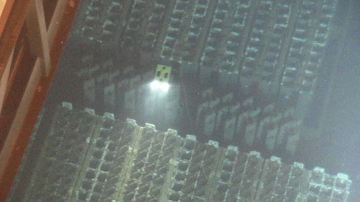
Using a remotely operated underwater robot to photograph the interior of the pool, submerged fuel rods and their storage racks were checked for any damage. A total of 615 spent and unspent fuel rods are stored in the pool.
White sediment was discovered on the aluminum alloy racks. It is believed to have formed from a reaction between aluminum and elements in sea water, which was injected into the pool to cool the nuclear fuel during the disaster.
Similar sediment was found in the reactor pools at units No. 3 and No. 4, from which fuel rods have already been removed, but according to Tepco it did not affect the process.
Similar to the No. 1 and No. 3 reactors, the No. 2 reactor suffered a core meltdown after it temporarily lost its cooling function in its spent fuel pool, but there was no hydrogen explosion at the building.
Because of that, the pool is thought to be free of debris and in a relatively stable condition.
High radiation levels on the top floor of the reactor building, where the fuel rods are located, have delayed cleanup efforts.
But progress in decontamination efforts has now enabled remote inspections to be carried out.
A new facility complete with a crane and equipment to lift out the fuel rods will be built on the south side of the No. 2 nuclear reactor building. The removal process is slated to begin sometime between fiscal 2024 and 2026.
https://www.japantimes.co.jp/news/2020/06/11/national/fuel-rods-fukushima-no-2/#.XuJIOufgqUk
Tepco completes survey of Fukushima Daiichi 2 fuel pool
 The ROV surveys the used fuel pool of Fukushima Daiichi unit 2 (Image: Tepco)
11 June 2020
There are no obstacles to the removal of assemblies from the used fuel storage pool of unit 2 at the damaged Fukushima Daiichi nuclear power plant, Tokyo Electric Power Company (Tepco) said today after completing an initial survey of the pool. Removal of the assemblies is scheduled to begin fiscal year 2024.
Similar to the reactors at units 1 and 3, unit 2’s reactor suffered a core meltdown after it temporarily lost its cooling functions, but the reactor building – which also houses the fuel storage pool – was spared a hydrogen explosion.
Using a submersible remotely-operated vehicle to investigate the fuel pool, Tepco concluded there was no damage to the fuel assemblies or the storage rack they are held in. It did, however, discover sand-like sediment at the bottom of the pool.
The utility said images captured during the pool’s survey will be used for designing equipment to be used in the removal of the fuel assemblies. It plans to start removing the 587 fuel assemblies from the unit’s used fuel pool between fiscal year 2024 (ending March 2025) and fiscal year 2026 (ending March 2027).
Dose levels on the operating floor of unit 2 are high, thereby making it difficult to access. Tepco has, however, already made progress with the clean-up of equipment, etc. that remains on the operating floor, providing access to the area near the storage pool.
It plans to complete the removal of all fuel assemblies from Fukushima Daiichi units 1-6 during 2031.
https://www.world-nuclear-news.org/Articles/Tepco-completes-survey-of-Fukushima-Daiichi-2-fuel
Tepco prepares to survey Fukushima Daiichi unit 2 fuel pool
 A worker receives training on using the submersible ROV
14 May 2020
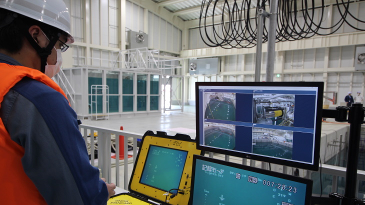
Tokyo Electric Power Company (Tepco) has carried out training in the operation of a submersible remotely operated vehicle (ROV) that will be used to investigate the used fuel pool of unit 2 at the damaged Fukushima Daiichi nuclear power plant. The investigation is scheduled to begin in mid-June.
The company said it plans to start removing the 587 fuel assemblies from the unit’s used fuel pool between fiscal year 2024 (ending March 2025) and fiscal year 2026 (ending March 2027). “However, prior to commencing fuel removal, we must first ascertain whether or not there are any obstructions above the fuel or inside the cask pit, and we must also ascertain the condition of the skimmer surge tank,” Tepco said.
Dose levels on the operating floor of unit 2 are high thereby making it difficult to access, Tepco noted. It has yet to conduct an internal investigation of the unit’s used fuel pool, but it has made progress with the cleanup of equipment, etc. that remains on the operating floor and it is now possible to access the area near the storage pool. Tepco has also now deemed it possible to safely install investigation equipment.
Tepco held training sessions at the Fukushima robot test field in Minami-Soma City for eight employees between 13 and 15 May on operation of the submersible ROV. It says the design of equipment for the removal of the fuel from unit 2’s storage pool will be reviewed according to the results of the investigation.
https://world-nuclear-news.org/Articles/Tepco-readies-to-survey-Fukushima-Daiichi-unit-2-f
Onagawa 2 upgrade faces further delay
04 May 2020
The completion of safety countermeasures at unit 2 of the Onagawa nuclear power plant in Miyagi Prefecture, in Japan, will not be completed until March 2023, two years later than previously scheduled, Tohoku Electric Power Company announced on 30 April. Japan’s nuclear regulator concluded in February the unit meets revised safety standards, clearing the way for it to resume operation.
Tohoku expects to spend about JPY340 billion (USD3.2 billion) on the countermeasures, which include seismic reinforcement of Onagawa 2 and construction of a 29-metre high and 800m long sea wall to protect the plant from tsunamis. The company had originally planned to complete this construction work by April 2017, but the schedule has been pushed back a number of times. The latest plan had been for the countermeasures to be in place by the end of financial year 2020 (ending March 2021).
However, Tokohu has now announced it has reviewed its upgrade works plan for Onagawa 2’s operation. Based on discussions it has had with the Nuclear Regulation Authority (NRA), Tohoku has decided to expand or revise its construction works for improving the facilities at the plant. As a result, the entire plan of construction work has been delayed and is now expected to be completed in FY2022 (ending March 2023).
Tohoku applied to the NRA in December 2013 for a safety assessment of Onagawa 2 – a 796 MWe boiling water reactor (BWR) – to verify countermeasures applied at the plant meet new safety standards. In late November 2019, the NRA approved a draft screening document that concluded the upgraded plant will meet revised safety standards, introduced in January 2013. On 26 February this year, the NRA approved the final screening report, clearing the way for the unit to resume operation. The utility is still required to complete the countermeasure upgrades and obtain the approval of local authorities before it will be able to restart Onagawa 2.
The Onagawa plant was the closest nuclear power plant to the epicentre of the earthquake and tsunami of 11 March 2011, but sustained far less damage than expected. The earthquake knocked out four of the plant’s five external power lines, but the remaining line provided sufficient power for its three BWRs to be brought to cold shutdown. Onagawa 1 briefly suffered a fire in the non-nuclear turbine building. The plant was largely unaffected by the tsunami as it sits on an elevated embankment more than 14m above sea level, but the basement floors of unit 2 were flooded. A mission from the International Atomic Energy Agency in August 2012 concluded that the structural elements of the nuclear power station were “remarkably undamaged, given the magnitude of ground motion experienced and the duration and size of this great earthquake”.
Tohoku has already decided to decommission unit 1 of the plant and is considering applying to restart unit 3.
https://www.world-nuclear-news.org/Articles/Further-delay-in-completion-of-Onagawa-2-safety-up
Fukushima Unit 2; New Containment Panorama Photos

April 1, 2019
A pair of new panoramic photos from inside Fukushima unit 2’s containment have been published. TEPCO provided the photos as part of ongoing updates on the disaster decommissioning work. The photos were stitched together from earlier containment inspection work then processed to bring out details of the photos. Also included in this report is details about the radiation and temperature readings inside containment, we explain that later in this report.
To read more on Fukuleaks:
Fukushima Daiichi Unit 2 Newly Erected Platform’s Enigma
A bird’s eye view of Units 1 and 2 from the hill
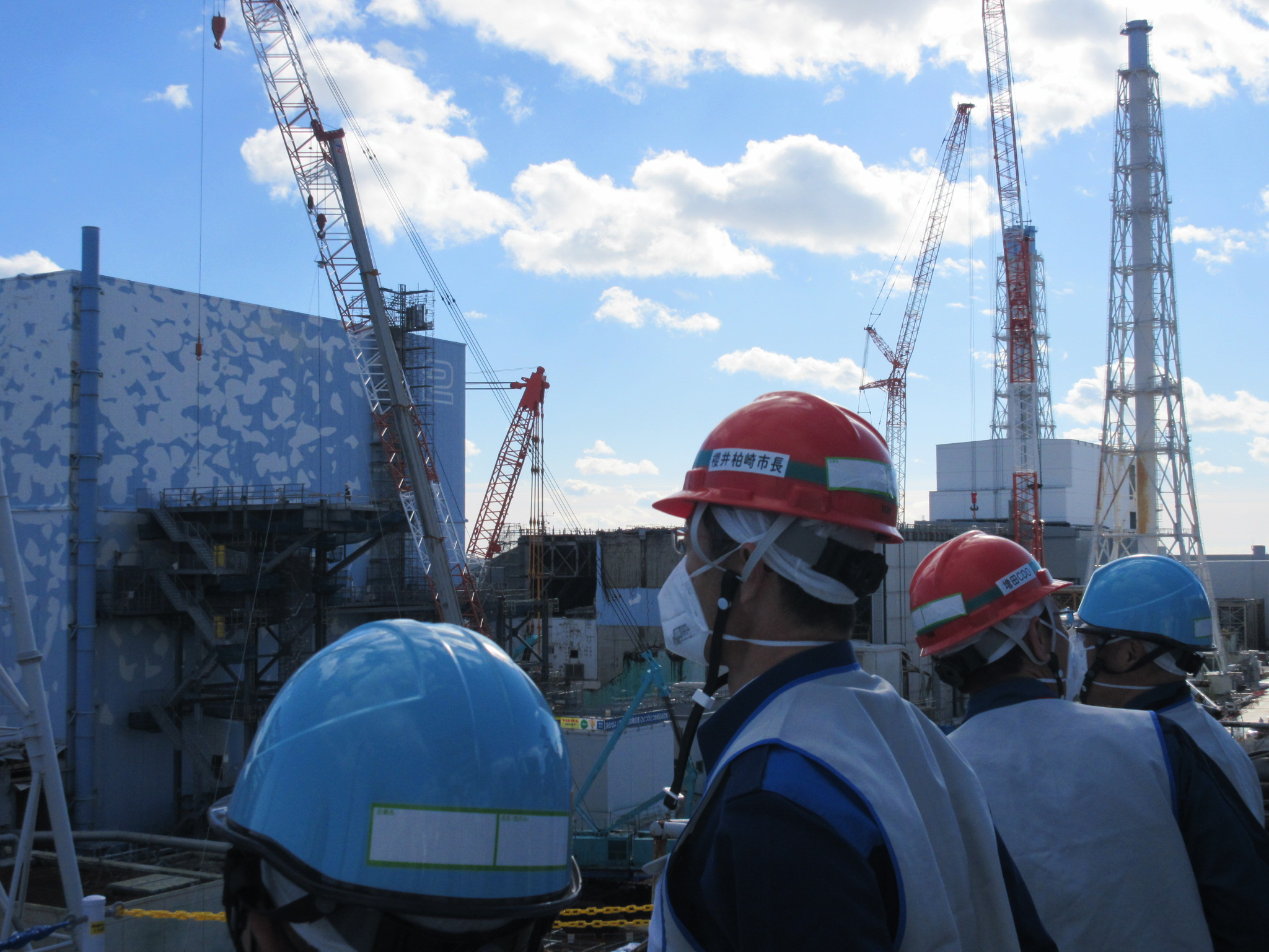
On December 15, 2016, the newly elected Kashiwazaki mayor, Mayor Masahiro Sakurai, who has called for a conditional restart of the Kashiwazaki-Kariwa nuclear power plant, one of the world’ largest nuclear plants, when he was elected mayor of this coastal city in Niigata Prefecture, northwestern Japan on Nov. 20, visited the Fukushima daiichi nuclear plant.
TEPCO, operator of the crippled Fukushima No. 1 nuclear plant, eager to restart reactors at the Kashiwazaki-Kariwa plant, invited him to tour the Fukushima Daiichi Nuclear plant, so as to show him that they fully control the situation there.
During the election campaign, Masahiro Sakurai said he would “approve a restart of the halted nuclear plant if safety is confirmed and certain conditions are fulfilled.”
One condition is the construction of a road that residents can use for evacuation in case of an emergency at the nuclear plant. Masahiro Sakurai also promised to start decommissioning older reactors at the plant.
Tepco made Mayor Sakurai visit the Fukushima Daiichi plant site, some of its buildings, its central control rooms 1 and 2, and the land side frozen by the impermeable ice wall.
On the same day, Tepco released 6 photos of Mayor Sakurai’s visit. One of the pictures was taken while Sakurai viewed Units 1 and 2 from the hill, it shows a new platform erected by Tepco around unit 2. This new platform with extensive stairwells and levels running the length of the building, might be part of some work to remove the refueling floor so as to replace it with a defueling building.

No information was yet provided by Tepco regarding that platform purpose.
Source : http://photo.tepco.co.jp/date/2016/201612-j/161215-01j.html
Containment Repair Research for Fukushima Unit 2 Ongoing
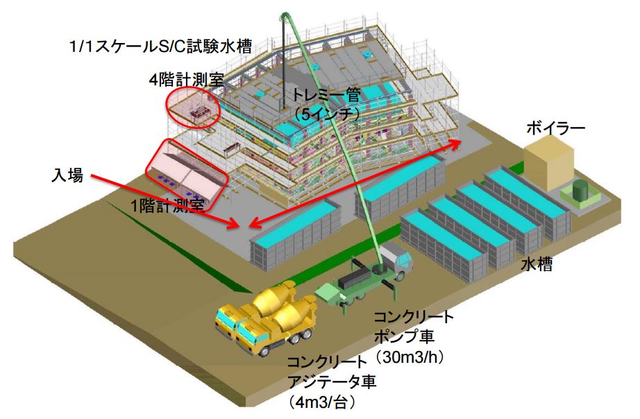
IRID announced the details of the ongoing research for repairing the unit 2 suppression chamber.
Based on their previous investigations IRID has determined that there could be a hole or series of holes of around 50mm in the unit 2 suppression chamber.
The research work is to determine if filling with concrete that structure could work. The proposed plan would use a concrete pump truck with a 5 inch diameter flexible hose to inject concrete into the suppression chamber.
Initial work took place at the Ando Hazama Technical Research Institute (Tsukuba City, Ibaraki Prefecture) on October 15th.
It seems they succeeded in layering the concrete mixture, sinking properly in the bottom of the suppression chamber tube. A 28 day pressure test will be conducted to assure the concrete properly plugs the leak.
Future work may be conducted at the new decommissioning research center at Naraha.
Source IRID :
<添付資料1:1/1スケールS/C試験に関する現場状況・概要図>
http://irid.or.jp/wp-content/uploads/2016/10/20161018_001.pdf
<添付資料2:コンクリート打設進捗に伴う時経列事象・解説図>
http://irid.or.jp/wp-content/uploads/2016/10/20161018_002.pdf
1 This Month
6 June – WEBINAR- Get Inspired by Protests Against Military Bases!


Cuba Is Not a Failed State – It Is a Besieged State
PETITION: “Global Appeal to Endorse Palestinian Right of Return of Refugees”


of the week– Nuclear Reactor Information Task Force
To see nuclear-related stories in greater depth and intensity – go to https://nuclearinformation.wordpress.com
-
Archives
- June 2026 (34)
- May 2026 (306)
- April 2026 (356)
- March 2026 (251)
- February 2026 (268)
- January 2026 (308)
- December 2025 (358)
- November 2025 (359)
- October 2025 (376)
- September 2025 (257)
- August 2025 (319)
- July 2025 (230)
-
Categories
- 1
- 1 NUCLEAR ISSUES
- business and costs
- climate change
- culture and arts
- ENERGY
- environment
- health
- history
- indigenous issues
- Legal
- marketing of nuclear
- media
- opposition to nuclear
- PERSONAL STORIES
- politics
- politics international
- Religion and ethics
- safety
- secrets,lies and civil liberties
- spinbuster
- technology
- Uranium
- wastes
- weapons and war
- Women
- 2 WORLD
- ACTION
- AFRICA
- Atrocities
- AUSTRALIA
- Christina's notes
- Christina's themes
- culture and arts
- Events
- Fuk 2022
- Fuk 2023
- Fukushima 2017
- Fukushima 2018
- fukushima 2019
- Fukushima 2020
- Fukushima 2021
- general
- global warming
- Humour (God we need it)
- Nuclear
- RARE EARTHS
- Reference
- resources – print
- Resources -audiovicual
- Weekly Newsletter
- World
- World Nuclear
- YouTube
-
RSS
Entries RSS
Comments RSS
